In our Fabricator General series, we talk about hobbying techniques and tricks, and ways to build, model, shape, and fix everything, with an eye toward information for both beginners and veterans. This week, Silks is talking about an advanced hobby project: Mechanizing a model using an Arduino board.
Hi and welcome to this article about using Arduinos to control electronics in models. While this process is a little complicated and the steps may look involved, note that before I started my first project with them I’d never used one before and had only really done work with electronics back in school. And yes, while I am a software developer by trade, writing the code needed for this project was a case of copy->pasting from Google and changing a few numbers around. So what I am saying is that despite how complicated this all looks, you really don’t need any special skills or knowledge to accomplish these effects, just the courage to give it a go!
What is an Arduino?
From Arduino’s website:
Arduino is an open-source electronics platform based on easy-to-use hardware and software. Arduino boards are able to read inputs – light on a sensor, a finger on a button, or a Twitter message – and turn it into an output – activating a motor, turning on an LED, publishing something online. You can tell your board what to do by sending a set of instructions to the microcontroller on the board. To do so you use the Arduino programming language (based on Wiring), and the Arduino Software (IDE), based on Processing.
What this actually means is it’s a way of programming various electronics to do things. You’ve probably heard of Raspberry Pis; Arduinos are very similar but designed to control electrical components (like LEDs, motors e.t.c) rather than power a retro games arcade.
Project Planning
Before you start working on something like this, you need a plan. A good way to build one is to start by asking yourself some basic questions.
What am I going to build?
Start here: What kit are you going to build? I spend a lot of time staring at models and decided that I wanted to do something cool with a Stompa since they’re so rarely seen (albeit with good reason, sadly).
What do I want it to do?
Here’s the fun bit. For my Stompa I decided I wanted the gun to “fire” and the chainsword to move. Once I’d decided to make the model move I thought I should probably make the head move too. For good measure I threw in some simple LEDs to make the eyes light up and the searchlight in his chest shine.
It’s best to split what you want to do into functions like that and then work out how to do each one. For this project I had:
- Gun firing
- Arm movement
- Head movement
- Basic lighting
By splitting it into functions like this you can work on each step separately and make sure each work.
How much room do I have in the physical model?
Your model will need to have the physical space to house the project components. The more components you need, the bigger the space (and model) you’ll need to work with. For this project the Stompa was an excellent choice since it has a huge hollow cavity in the middle to work with (and it’s made of easy-to-work-with plastic). If your project doesn’t you’ll have to construct a base (a mausoleum from the Gardens of Morr kit makes an excellent electronics housing) and run the components through the model. Bare in mind that you’ll need space inside the model somewhere for the electronic component you’re powering to sit, but you can generally hollow out a space yourself with hobby clippers. For my Spirit of Durthu for example I assembled the parts around an LED and kept clipping and filing until there was a big enough cavity for it to sit. You’re not going to fit a motor in the arm of a dreadnought, but you might fit it inside the body.
Editor’s Note: For a project that uses electronics and wiring with much smaller models, stay tuned for a future article where we’ll showcase Merton’s LED Necrons.
How do I make it do that?
Next you’ll need to do a little research on how to accomplish what you’re looking for. For this project, I spent a lot of time googling “how to make something move with an Arduino” (and similar queries). Almost anything is possible here, especially if it has already been done before. You just need to find the right tech.
Movement
You’ve really got two ways of making something move electronically: A motor or a servo.
- A motor is, as you might expect, something that continuously spins an axle. If you ever used Lego Technic you’re probably familiar with these little motors for driving things like helicopters or windmills. If you’re building something like a gatling gun then attaching the barrels to the axle will make them spin round (and add a satisfying noise too).
- A servo is more like a speedometer in your car. You can make it move from left to right by varying degrees. This is more suited to moving an arm up and down or making a hatch open and close.
Control Lighting
While I’d love to make the gun actually shoot something, we’re playing Warhammer here, not Robot Wars. So we’re looking for simulating a big gun shooting. Pulsing LEDs are ok but guns don’t often pulse. I decided to go for a string of LEDs firing in sequence to look like the shot was going down the barrel. You could also use it for a “startup sequence” for a tank or a ring of LEDs around the edge of a spooky monolith.
Play sounds
I didn’t end up using any sounds in my Stompa, but my next Arduino project is going to involve playing a .wav file. This is done by loading it onto an SD card and attaching a speaker. You could load the card with gunshot noises, dramatic music, you shouting “WAAAAGH” at the top of your voice, etc.
Loads of other things
There are loads of examples of components out there that people have found clever uses for. Sign up to some Arduino forums or take a look at component sites and see what is available. Some things that jump out to me are:
- Tank tracks – need I say more? Your tank can actually move!
- Lasers – can anyone say Markerlights?
- Infrared Range Sensors – want something dramatic to happen when you get into charge range?
- LED matrix displays – Did you buy a stupid Mekboy Workshop? Why not use it to show how many command points you have left?
Choosing Components
The first thing you’ll need for this project is an Arduino. This can be a daunting process. There are plenty of Arduino clones and most of them are pretty good. This is because of the open source nature of Arduino — these aren’t actually dodgy so don’t feel like you have to stick to the branded ones. Do check the reviews though as the cheaper they are, the more likely they are to have faulty wiring and other issues. Some thoughts on these:
- Uno: This is the best Arduino for a beginner. It’s got a power socket and USB input built into the board meaning you can plug it straight into your computer and load some code onto it. It has enough outputs that you can control several different things at once.
- Nano: This is a much smaller version of the Uno. It doesn’t have an inbuilt power socket and just has a micro USB input so while you can run it when plugged into your computer you will need to wire some batteries to the relevant pins. Not too complicated but a little hurdle in getting started. Would be much easier to fit inside a smaller model like an Ork plane, though.
- Mega: If you’re planning a really complicated build then this gives you many more outputs to control many different things. It’s also really big so you’re typically only working with one of these on very large projects like display boards.
There are loads of other options including ones with WiFi built in and even some promising they include “artificial intelligence”. I think the Mechanicum’s prohibition of that is probably very wise in this case for now; you don’t want your Baneblade going rogue.
The other important things are a breadboard and some wires that will easily go into it so it’s well worth getting a kit that includes these. There are some great starter kits out there – this is the one I got, which also includes LEDs, resistors and a few other bits. If you’re unfamiliar, a breadboard is simply a piece of plastic with lots of holes in it, with copper running along the bottom of each row so you can build up a circuit without any soldering (making it much easier to move stuff around when you get it wrong).
After this it’s a case of picking components. The only other things I needed were some flickering LEDs (this is built into the LED itself so no need for anything complicated) and some Servos to move things. I bought a cheap pack of 4 of these from eBay.
Making the Electronics work
At last, the fun bit! You get to build your giant model. Sorry, nope. Not yet. First of all you want to get your electronics all working outside the model.
My first Sketch
First of all, I connected up the Arduino to my laptop and loaded up the IDE which I’d installed the laptop. You write code in “Sketches” and then push them onto your Arduino via the USB cable. Luckily there are plenty of examples included. The best one to start with is “Blink” so open that up from the File > Examples menu and then upload it to your board (via the Sketch menu). When you reset your Arduino the onboard LED should start to blink. You can now unplug it from the computer and plug a 9V battery connector into the power supply and it will run this code forever more (well, until the battery runs out anyways).
Trying something a little more complicated
Now, I took a look at the code. There is a void setup() and a void loop(). The setup void is where we initialise our components, basically mapping them to a pin on the Arduino and the loop is the continuous code that runs when the Arduino is powered on.
If you’re comfortable coding, good for you, but as a programmer for 20 years I know full well that it’s a lot easier just to google code and adapt it for themselves.
Here’s my next, slightly more complicated attempt:
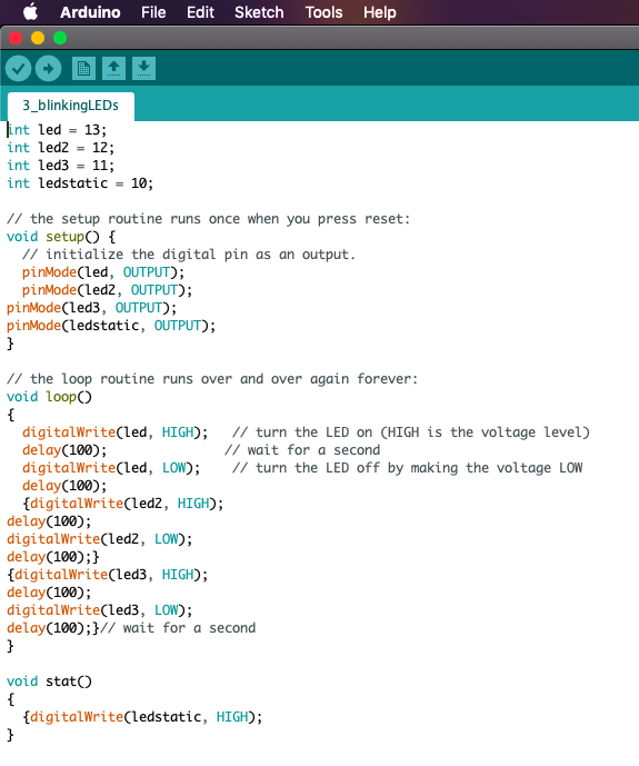
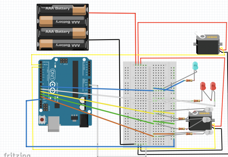
Of course, we need some electronics too, so I set up 3 white LEDs in my breadboard, connected them to the Arduino pins above (including a resistor so I didn’t blow the LEDs) and gave it a go. After a bit of trial and error I managed to get them “firing” in a row with a second in between which repeated itself forever. It also includes a “static” LED (actually two LEDs wired in series) which are always on for the eyes and the searchlight. I changed the colour of the searchlight to green later on (just swapped out the LED)
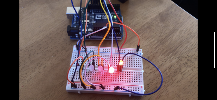
That’s the lighting done!
Movement
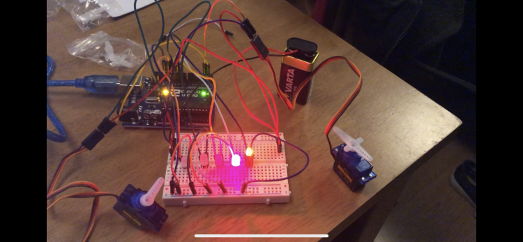
Now onto the bit which I really didn’t know much about, the servos. I started off by reading a few guides about how to wire them up and how to make them move. Turns out they’re a lot like a clock, where you set their initial position and then tell them to increase in degrees by a certain amount until they reach their finish position. So, doing my best professional coder work I found some code online for how to make them move and got them doing what I wanted. However, I also read lots of people warning that the power output of the Arduino isn’t enough to power more than one servo without the chance of frying it, so I instead wired up a bunch of AA batteries and ran the power to the servos from that instead of the power pins on the Arduino. Note – at this point I haven’t built any of the model, this is all done just on my desk.
Getting it all in the model
Building the Model around the breadboard
So now I’ve got the electronics doing what I wanted them to, it’s time to start building the kit. I built most of the body of the Stompa, leaving the chest plate, arms and head off. This shell is what I needed to fit everything into.
I then built the gun up. Whilst building it I used clippers and a drill to run wires all the way down the arm and into the gun, then soldered them onto the LEDs I’d taken out of the breadboard. I then ran the wires down into the now empty positions, checked it all worked (and I’d got them in the right order) and glued the gun up and attached it to the model.
Next it was time to put the servos in. I created a fairly sizable hole in the neck and poked the servo’s axle through, then glued one of the little plastic attachments that slots onto the axle to the bottom of the headpiece. This came with the added bonus that the head is removable! I did exactly the same with the arm, but rather than using the arm itself I gave it a quick test with a wooden chopstick bluetacked to the servo.
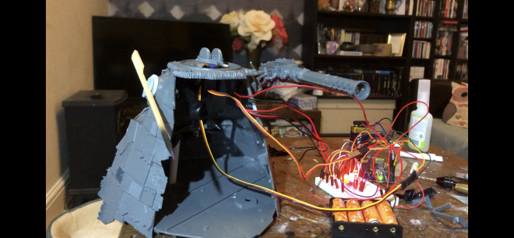
While this worked and indeed made the chopstick and head move, it was clearly only just about able to handle the weight of a chopstick and bluetack; there was no way it was going to cope with a heavy chainblade arm. So I went onto eBay and found a much more powerful servo. This arrived and was huge and heavy… I tried putting it through the arm hole but it just sagged and fell out. So, out came my plasticard collection and I fashioned some internal scaffolding with a platform to hold the heavy servo in place (with some electrical tape wrapped round it to make sure it didn’t fall off). I then did the same with the servo for the head using some bits of sprue to brace it. This was enough to hold the arm, which I superglued to a large circular bit of plastic and very delicately superglued onto the axle (if I’d have got some glue inside the servo things would have gone badly!).
Lastly I ran one of my static LEDs through the hole in the neck and built the head around it so that the eyes would glow. I removed the plastic searchlight in the front panel, glued my green LED in place, and used some greenstuff to build up the cage that was originally sculpted on.
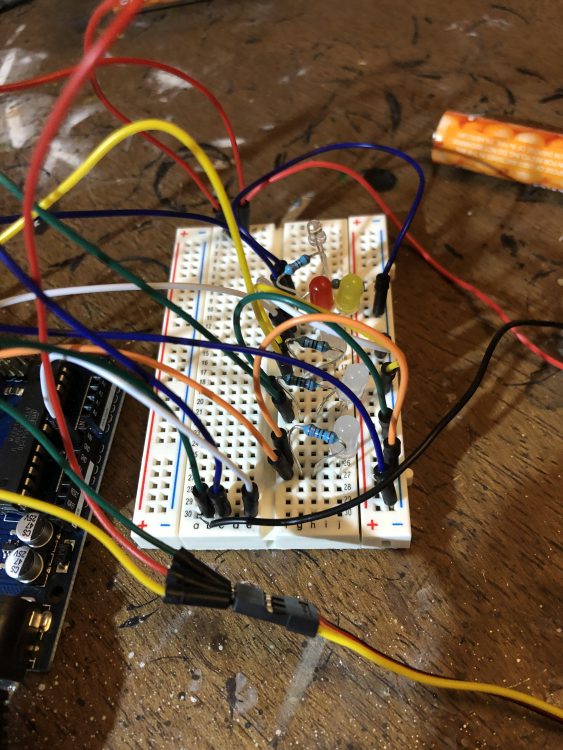
Integrating the Circuit
I’ve got the model doing everything I wanted it to! But I still have loads of wires coming out of it into the breadboard. I could just shove it all in, but the connectors are meant to be easy to remove so will just fall out. So instead I needed to move it to a “protoboard”. This is exactly the same as a breadboard but needs soldering rather than just popping the components in.
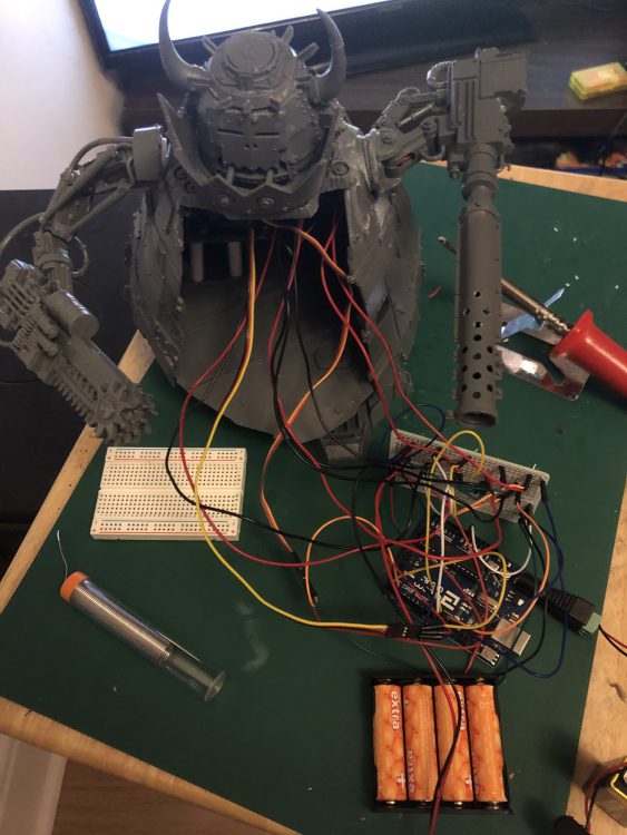
I am not the best at soldering, but luckily the process here wasn’t too complicated. Just replicate your breadboard one by one, use a soldering iron (less than a tenner from Wilkos) to heat up the bit of wire that pokes through and when it’s hot enough apply some solder and it should just “blob” on.
Enclosing it all
Hurrah, the model is built and is now going to run permanently when I plug in the batteries. But it’s still got a massive hole in it. I drilled some magnets into the body where it connects to the front panel, put a spot of paint on each one and pressed the panel into place before it dried. Then when I took it off it had little blobs of paint where I needed to put magnets in the panel to make it fit. I also put an “on off” switch which I wired up directly into the red wire from the 9V battery and pushed it through a hole I cut in the back (which I then covered with one of the many spare bits of paneling from the kit, which was again magnetised). This would mean that I could turn it on and off without needing to take the batteries out each time.
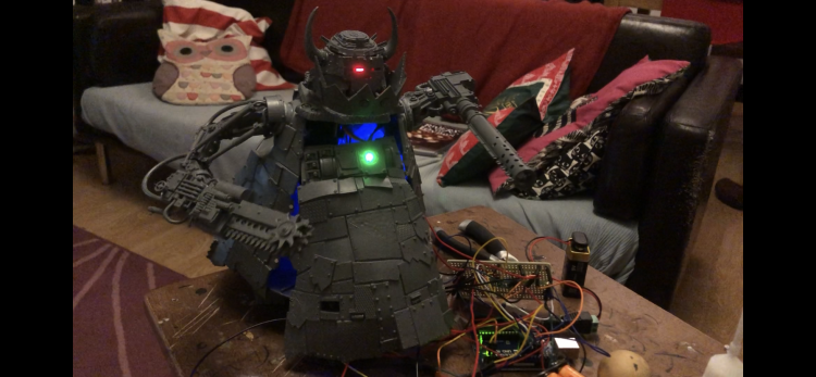
One last test and I could shove all of the electronics and batteries inside the model and pop the covers on!
After that, it’s just a case of painting the thing. Make sure to cover all your LEDs with masking tape or bluetack when you do!
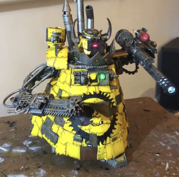
The finished product
Feel free to take this and adapt / use it yourself!
#include <Servo.h>


Servo myservo1;  // create servo object to control a servo Servo myservo2;  // create servo object to control a servo // twelve servo objects can be created on most boards


int pos = 0;    // variable to store the servo position

int led = 13;

int led2 = 12;

int led3 = 11;

int ledstatic = 10;

int ledflicker = 9;

int randdelay;

int motordelay;

int totdelay;


// the setup routine runs once when you press reset:

void setup() {

  // initialize the digital pin as an output.

  pinMode(led, OUTPUT);

  pinMode(led2, OUTPUT);

pinMode(led3, OUTPUT);

pinMode(ledstatic, OUTPUT);

pinMode(ledflicker, OUTPUT);

myservo1.write(90);

myservo2.write(90);

  myservo1.attach(1);  // attaches the servo on pin 9 to the servo object

  myservo2.attach(2);  // attaches the servo on pin 9 to the servo object }


// the loop routine runs over and over again forever:

void loop()


{


  //turn on static LEDS

  stat();


    randdelay = random(10);

    motordelay = random(15);


  //Gunfire

  delay(2000 * randdelay);

  digitalWrite(led, HIGH);   // turn the LED on (HIGH is the voltage level)

  delay(100);               // wait for a second

  digitalWrite(led, LOW);    // turn the LED off by making the voltage LOW

  delay(100);

  {digitalWrite(led2, HIGH);

  delay(100);

  digitalWrite(led2, LOW);

  delay(100);}

  {digitalWrite(led3, HIGH);

  delay(100);

  digitalWrite(led3, LOW);

  delay(100);}// wait for a second


    //Random firing timer

    totdelay = randdelay * 1000;

    delay(totdelay);


  //lift the arm


   pos = 90;

   myservo1.write(90);


    for (pos = 90; pos <= 135; pos += 1) {

    // in steps of 1 degree

    myservo1.write(pos);

    delay(75);

                                        }


    delay(5000);


  for (pos = 135; pos >= 45; pos -= 1) {

    myservo1.write(pos);

    delay(75);

                                      }


    delay(5000);


    for (pos = 45; pos <= 90; pos += 1) {

    // in steps of 1 degree

    myservo1.write(pos);

    delay(75);

                                        }


    //move the head

    pos = 90;


    for (pos = 90; pos <= 135; pos += 1) {

    // in steps of 1 degree

    myservo2.write(pos);

    delay(75);

                                        }


    delay (5000);


  for (pos = 135; pos >= 45; pos -= 1) {

    myservo2.write(pos);

    delay(75);

                                      }


    delay(5000);


   for (pos = 45; pos <= 90; pos += 1) {

    // in steps of 1 degree

    myservo2.write(pos);

    delay(75);

                                      }

      delay(1000 * motordelay);


}


void stat()

{

  digitalWrite(ledstatic, HIGH);

  digitalWrite(ledflicker, HIGH);

} ;
Hopefully that’s given you the knowledge and the courage to start playing with more electronics than just an LED.
As always, if you have any questions, comments, or tips of your own, feel free to share them in the comments below. Or email us at contact@goonhammer.com. Happy hobbying!
