Turn your physical models into digital 3D models in this guide to photogrammetry. This third article covers turning your photos into a 3D model with 3DF Zephyr.
Time for another article on Getting Started with Photogrammetry, and this time it’s all about creating a rough 3D model from pictures. This article is a bit longer than the previous steps, but we also have a lot of ground to cover. If you’ve been following along then, last time in the second article, you’ll have cleaned your photos and have them ready to go.
If you are new to this, go ahead and start at the first article and work your way through them. As a summary though, this series is a guide on how to turn your physical models into 3D models and import them into Tabletop Simulator.
The Tools We Need
Now that we have our clean photos, let’s turn them into a rough 3D model. The software we’ll be using for this is 3DF Zephyr (https://www.3dflow.net/3df-zephyr-photogrammetry-software/). Fortunately the free version will work just fine for our purposes.
Additionally, if you want to use your 3D model in online games, you’ll want Tabletop Simulator (https://store.steampowered.com/app/286160/Tabletop_Simulator/) installed. We’ll be using it at the end of this article to check our work, making sure the model loads successfully.
3DF Zephyr
Before we dig into using it, I want you to know that Zephyr is software which is under active development. If you install the latest version right now, the UI might not line up 1:1 with the screenshots in this article. At least one update has been published to Zephyr between now and when I took the screenshots for this article. I’m optimistic that the large part of these instructions all still line up though, because goodness me it’s been a lot of work organizing this information.
As complicated as this process has been and yet still is, 3DF Zephyr is fortunately a fairly linear piece of software. From aligning photos, generating point clouds, to creating the final mesh; each step directly builds off the previous step. You don’t typically go back a step unless you are correcting a mistake.
To that end, when correcting mistakes you get better results the earlier in this workflow you address the problem. If you wait until near the end (textured mesh generation) to correct a glaring mistake, then your final result will look much worse than if you correct the mistake near the beginning of the process (sparse point cloud). This is actually so important that I’ll frequently go back a step or two while fixing issues rather than pull my hair out trying to correct it later on.
First things first, we need to get our photos into the software.
New Project and Importing Photos
Launch this magical software and go into Tools > Options > Appearance and check Use OS native file dialog. Ain’t no one likes custom file dialogs. Ain’t no one.
To actually begin the project, go to Workflow > New Project.
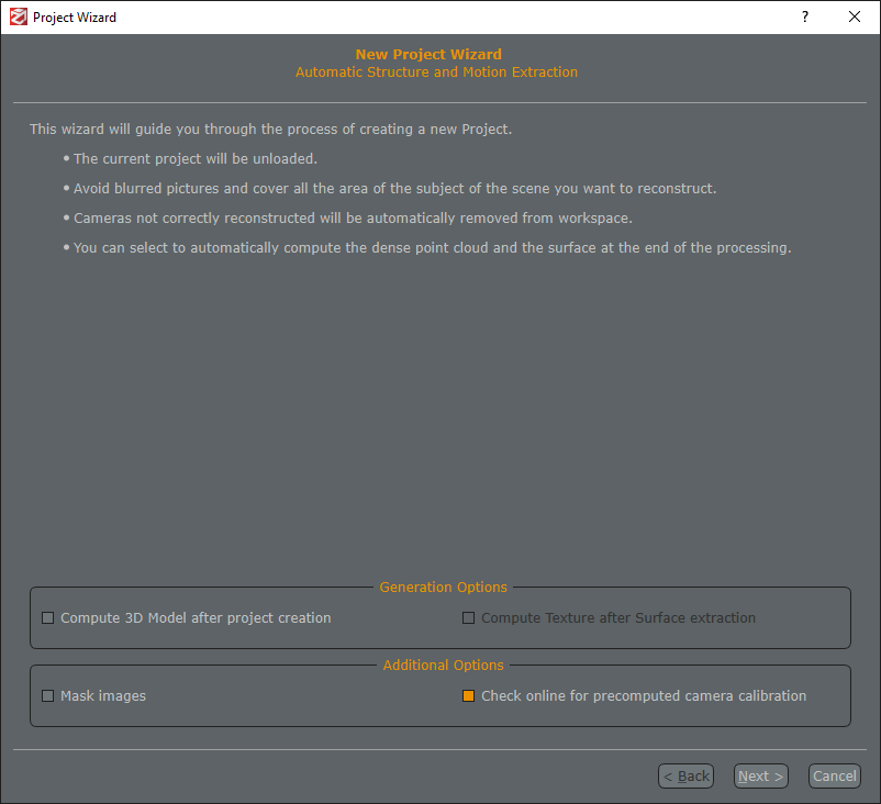
Make sure the generation options are off, as we’ll be performing manual cleaning in between each step. I don’t know what “precomputed camera calibration” is, but leave it checked I guess?
If you cleaned and masked the photos with Photoshop, Gimp, or some other software, then you don’t need to check the Mask images box. However, if you don’t have a high quality photo set up, access to Photoshop, or the mental fortitude to learn Gimp (I certainly don’t), then try going through the following steps with the images you have. Zephyr is pretty good software, and might be able to process your pictures without issue.
If, however, you find that Zephyr just cannot work with your images as-is, you can use a bundled piece of software, 3DF Masquerade, which is free software specifically built for masking images. To use this, check the Mast images button, and Zephyr will launch it. While it isn’t terribly difficult to use, it is rather time consuming. Unfortunately I have extremely limited experience with Masquerade, so the best advice I can offer is to use the Mask From Color tool, pick the background color, tweak the threshold until it’s close, and then use the lasso tool and the Numpad + and Numpad – keys to adjust it by hand. You can automate the “Mask From Color” portion, but tweaking by hand is a long process.
Assuming that you now have pictures that are nice and clean, click Next, add all your cleaned images, and click Next again. Now we have to enter all the settings for the project wizard. If you don’t see these settings, change the Settings in the top right to Advanced.
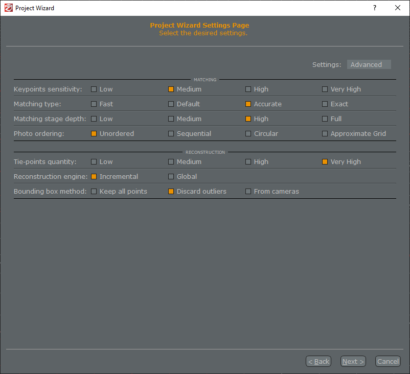
I would sure love to tell you what all these settings meant, but I’m both Not Good as well as Bad at this software. The above picture are the settings I use for my photos. Some were defaults, some from random online resources, and some were guess, check, and happenstance. Click Next and prepare for a wait. This could be take anywhere from 5 minutes to an hour, depending on your computer. Also note that this is fairly GPU intensive, so you might have slowdown if you switch over to Netflix. To be clear, I still alt-tab and watch stuff, but I just want you to know there might be a slowdown.
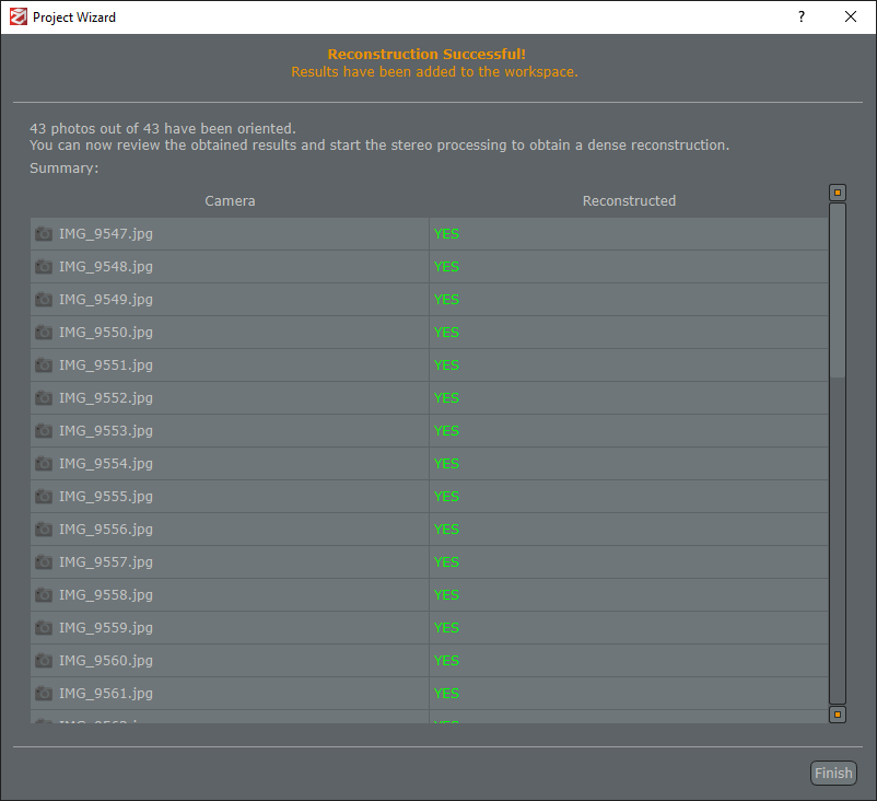
If everything went well, you should be greeted with a screen like this. We really want to see nothing but green YESes, as each represents a photo that 3DF Zephyr was able to use. If you see red NOs, then that means 3DF Zephyr couldn’t use that photo and there was a problem.
One or two NOs isn’t the end of the world, but if you’re getting a lot of them, then I would recommend going back to this article’s section on Cleaning Photos. If your photos look fine, but Zephyr still can’t use them in reconstruction, then take a look at 3DF Masquerade to manually mask these photos for better scanning.
Sparse Point Cloud
If the photos are imported successfully, you should have a sparse point cloud now. This is a set of colored dots in 3-dimensional space that form a “cloud” of the model. It’s called “sparse” because it’s sparsely filled, as opposed to the “dense” point cloud we’ll be generated later.
To better see these points, go to Tools > Options > Rendering > Point Clouds > Sparse Point Size and increase the slider a couple notches. Might want to bump up the Dense Point Size as well, though this is entirely personal taste.
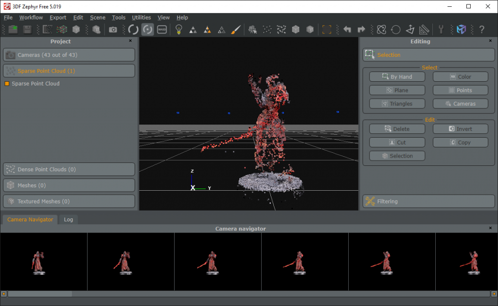
If there are issues, don’t panic. The most common issue at this point is that the front half of your model and the back half aren’t aligned correctly. As I mentioned in the last article, this can happen if too many background details were cropped out of the pictures. 3DF Zephyr uses these details to align the photos, and without a proper frame of reference, it might misalign things. If this happened, try importing the raw pictures from your camera without touch-ups. Or remove background detail, but leave the lazy susan in place. This might cause 3DF Zephyr to take longer when processing the images, but it should result in more accurate image alignment.
Assuming things look good so far, click File > Save As to create a .zep file to store what you have so far. Save this into the project directory you created for this project, the same folder as all your pictures. You’ll periodically want to resave it, just so you don’t lose your progress.
As for the model, to look around it, there are three basic commands in Zephyr:
- Left click and drag: Rotate around a point
- Middle click and drag: Pan the camera around
- Scrollwheel: Zoom in and out
Once you’ve mastered the art of twirling about, look around the sparse point cloud to make sure it very roughly looks like the physical model. Remember that this is a “sparse” cloud, so your model will look like it’s in the middle of being snapped away, but and that’s okay.
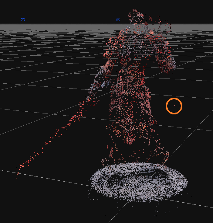
While rotating around the model, you might notice random dots floating in the middle of nowhere that don’t correspond to a real point on your real model. As an example, look at the dot circled in orange above. These are artifacts that the software generates when specks of dust or reflections confuse it.
When you find these points, selecting them with the Selection > By Hand > Lasso tool (or whichever tool you prefer), and press delete to get rid of them. Start conservatively with this process, though. It’s always easier to edit this sparse cloud again in the future to remove a couple extra stray dots, rather than removing too many and forcing yourself to import all the photos again.
Dense Point Cloud
Let’s get dense. As the name implies this is a point cloud, similar to the prior step, however it’s dummy thicc with points, and it’s the next step in the workflow. When your sparse point cloud is looking good, go to Workflow > Advanced > Dense Point Cloud Generation. Change the Settings in the top right to Advanced.
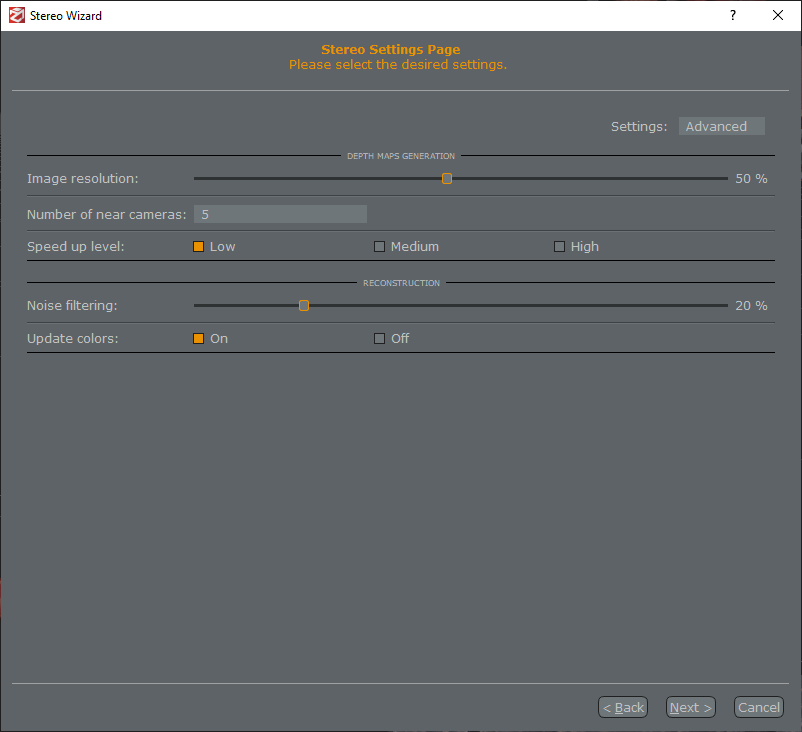
Honestly, I don’t know what the majority of these settings do. However, I know that they coincidentally work for me, so ¯\_(ツ)_/¯
Let this run for a while and you’ll wind up with another point cloud, except this one is denser. Here is also the step where you’ll begin cleaning the model in earnest.
I mentioned it earlier, but now is a good time to repeat it, the earlier in this process you clean the model, the better the final product will be. Sure, you can wait until you are in the very last stages to do cleanup, but it’s going to be a miserable amount of work. The earlier you correct stuff, the better.
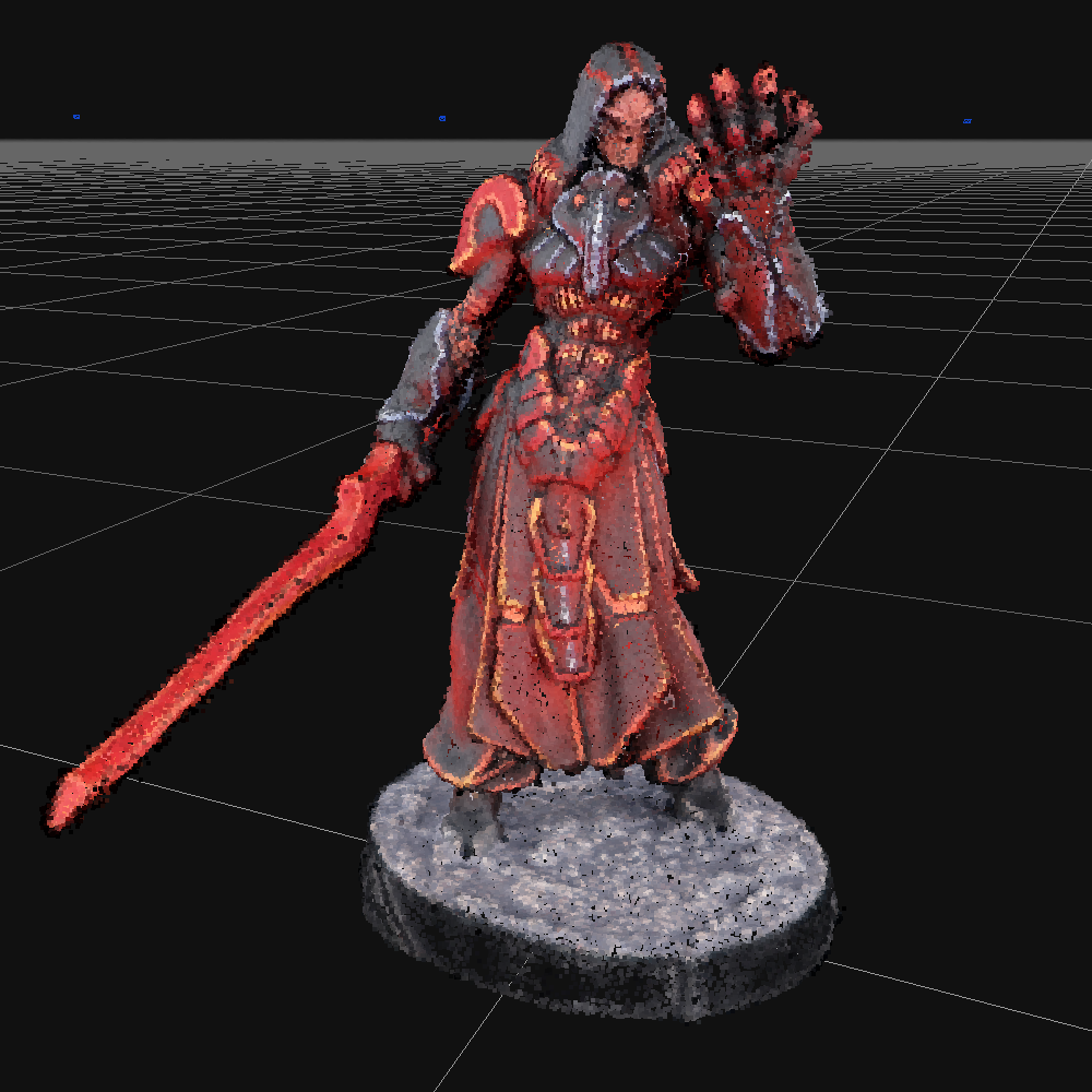
Before you edit the dense point cloud, go ahead and create a clone of this. Do this by going to the left-hand Project panel, right clicking the dense point cloud, and clicking Clone. This gives you something to fall back to if you completely ruin things. Once you have a clone, untoggle it with the little checkbox to make sure you are only editing one of them.
As for editing the dense point cloud, there are a lot of things to look out for:
- Misaligned Geometry
Sometimes Zephyr gets confused and accidentally joins two different objects. It’ll put little black points between a cloak and an arm, a backpack and a back, or in the hollow of something, well, of something hollow. Delete these points as they can cause issues that are a pain to fix later. - Backdrop Bleed
This software does a good job when distinguishing the model from the backdrop, but it’s not perfect. Bits of the backdrop will occasionally show up, silhouetting the model at odd angles. They are pretty easy to spot if you took photos against a white backdrop, at the white points will stand out. However, if you took your photos against a black backdrop, then you’ll want to spend some time rotating around the model, and looking for black points you can delete.
You don’t have to be perfect with cleaning the dense point cloud. Areas like under a model’s armpit really aren’t that important, as those areas are virtually unnoticeable when imported into Tabletop Simulator. However, pay attention to areas that are highly visible: heads, shoulders, weapons, that sort of thing.
Rule of thumb: if you are fine with the area rendering as a patch of pure black, then it’s fine to leave the black points in.
Rim of the Base
This is a point of contention. If you want your 3D model to perfectly represent your physical model, then go ahead and leave the base rim on. However, removing the rim of the model’s base imparts a ton of benefits, and I highly recommend it. If you remove the base, you can replace it in Tabletop Simulator with an existing base that’s scaled to be exactly the correct size and shape (scaling the model is something we’ll get to). Additionally, having a separate base lets you color and texture it independently from the model, handy for “the red one is the sergeant” moments.
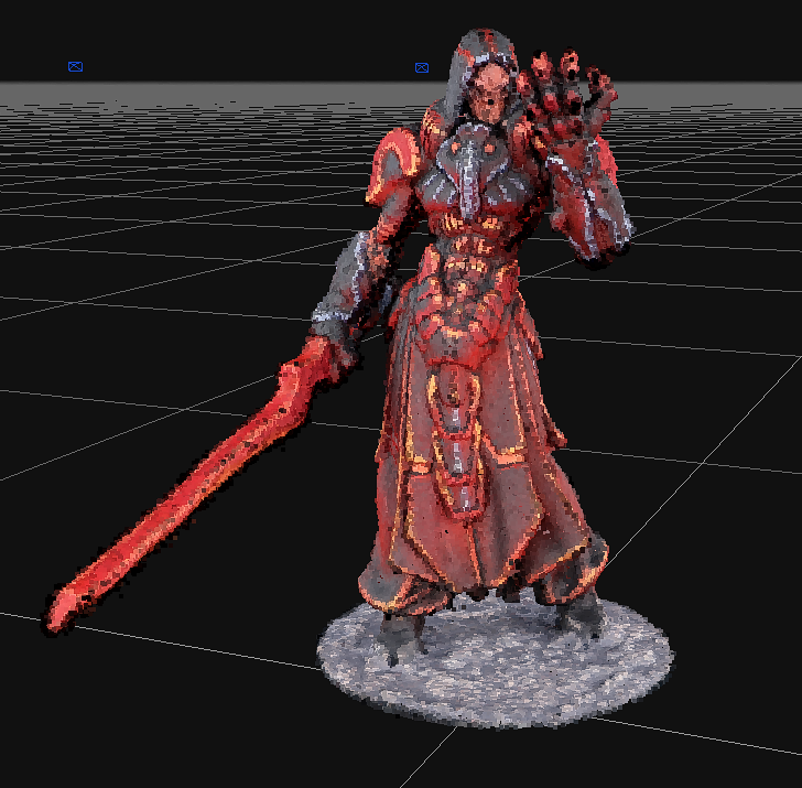
Use the Plane selection tool, and align it so that it slices off the sides of the base, but leave the top of it intact. Press “Update” on the Plane tool, and you’ll notice that it probably selected all the points which you want to keep, rather than the points you want to delete. If that happens, press the “Invert” button to flip the selection. Once you have the points you want to ditch, then click “Delete”.
Mesh Extraction
Once you are happy with your dense point cloud, click Workflow > Advanced > Mesh Extraction. Change the Settings in the top right to Advanced.
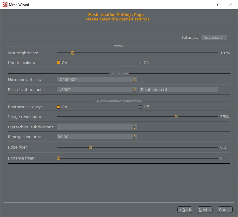
As before, these settings are all magic to me. They happen to work for my setup, but feel free to experiment. This should take a decent amount of time to run, and once it’s complete go ahead and clone it as you did before, just to have something to fall back to.
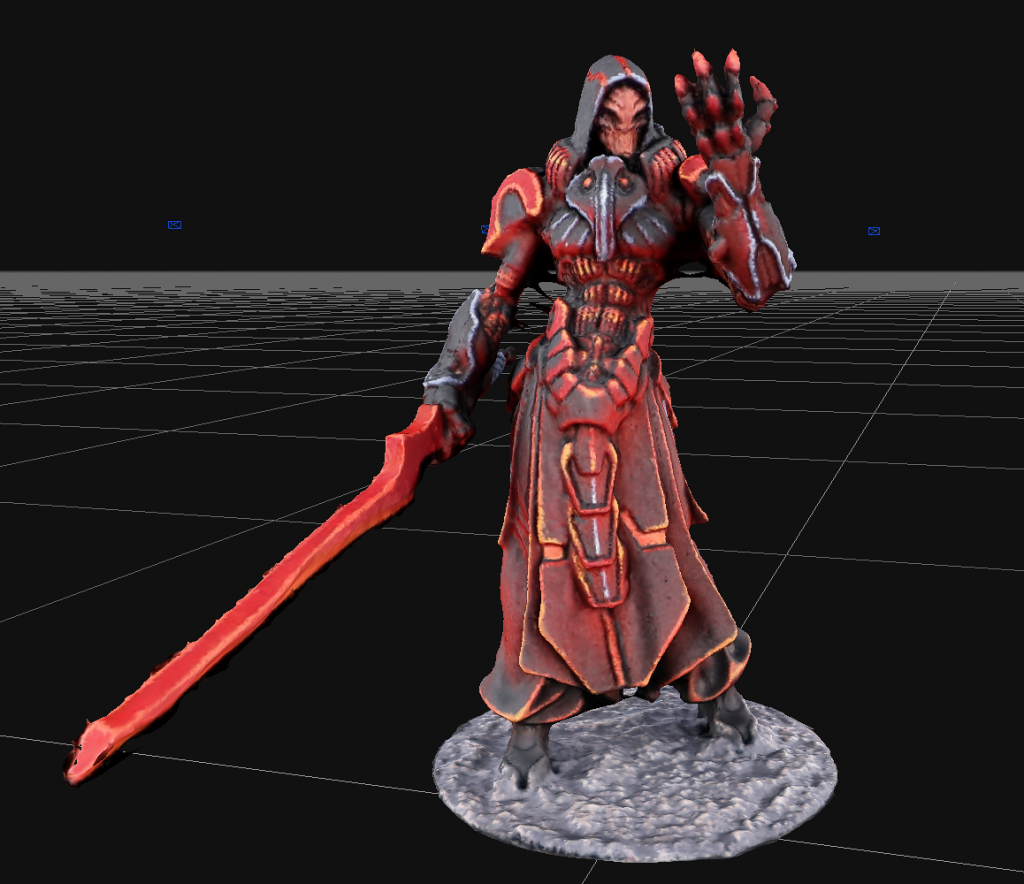
And we have our first mesh! Take a minute to look over the model and appreciate your hard work. Go you! Also keep in mind that this isn’t the final product. The final mesh will be higher resolution.
When looking at the mesh, you might also notice some issues with the model. If there are large glaring ones, you can go back to either the sparse or dense point cloud, remove some erroneous points, and regenerate the mesh. But for some smaller issues, there are pretty easy ways of fixing them right now.
Cleanup – Removing Spikes
One of the errors you might see are spikes in the model.
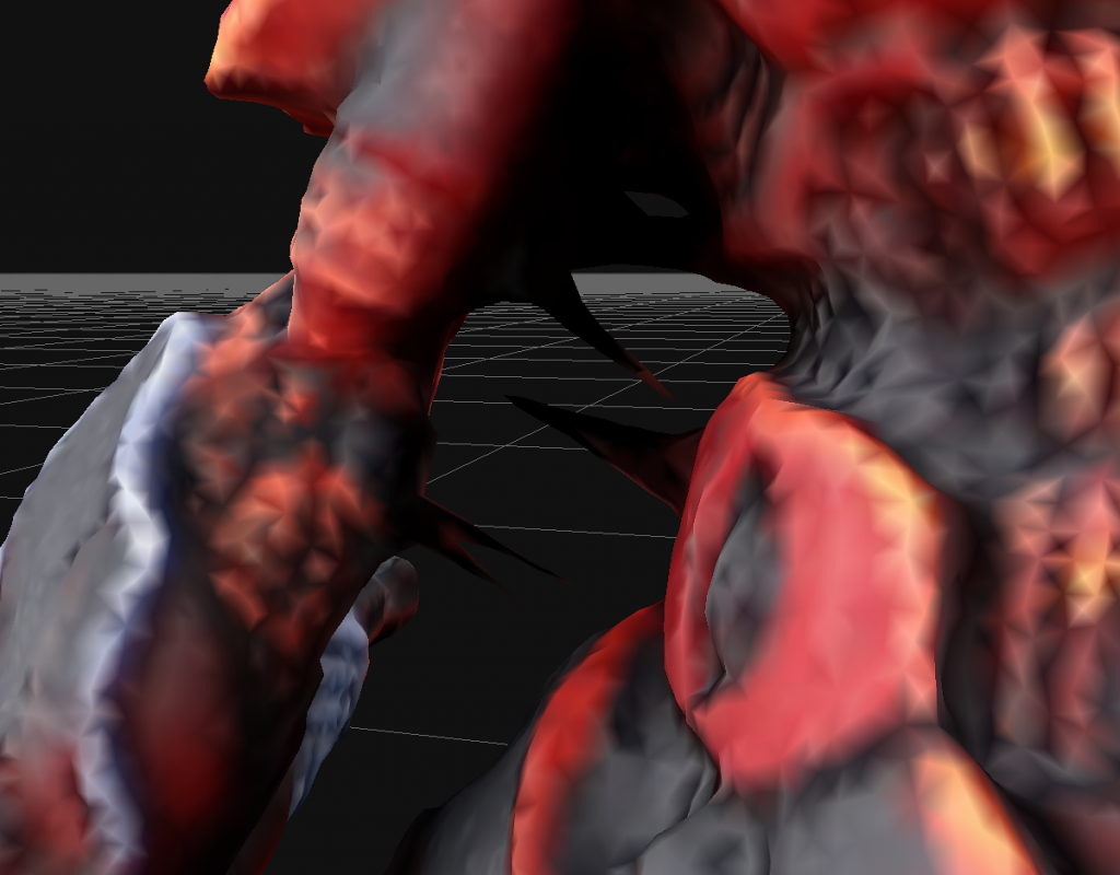
For spikes larger than these, it might be worth going back to the dense point cloud and deleting the points that are causing the error, and then regenerating this mesh. However, for spikes of this size, it’s pretty safe to just delete them.
Using the lasso tool (remember, Selection > By Hand > Lasso), select the spike (and only the spike) and press delete. To fine-tune your selection, you can toggle between Add and Remove mode to add and remove selected areas before pressing delete.
Cleanup – Filling Holes
When you delete these spikes, you’ll notice that it’ll produce holes in your mesh.
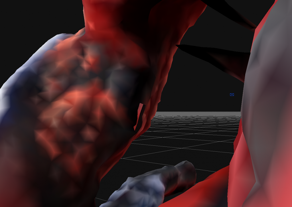
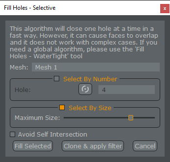
You’ll want to fill holes now, which is fortunately easy to do. In the Project panel on the left, right click the mesh and select Filters > Fill Holes – Selective.
This part is a little weird, but hear me out. Earlier, if you cut away the rim of the base, then the model will have a hole on the bottom. And in fact, this hole on the bottom is fine (at least, it’s never given me issues). So when you delete a spike, the model will now have two holes in it: one from the spike, and one from the base. If you delete n spikes, you can expect n+1 holes. Follow? So we want to fill but one hole using this tool, and fortunately, that’s pretty easy.
To do this, check the box next to Select by Size, and then drag the Maximum Size slider all the way to the right. Then bring it a single tick to the left. It’s a fair assumption that the hole in the base is the largest, so leaving the slider here tells Zephyr to fill all other holes in the mesh other than the one in the base. Click Fill Selected and check each hole to make sure it filled them correctly.
Sometimes Zephyr fills holes in really odd ways, making things worse. If that’s the case, leave the hole in place as we can fix it in Blender later. But try to fill as many as possible now, as Blender is nowhere near as friendly as Zephyr.
Retopology
After you’ve cleaned up the model to the best of your abilities, it’s time to compress it to a size that will fit within Tabletop Simulator’s restrictions. You might ask what are the precise restrictions, and that’s a good question. I don’t know the answer to this question, but it is a good question. Seemingly nobody really knows, as depending where you look, you’ll read different numbers measuring different things. But I can at least show you my process for getting results that consistently work.
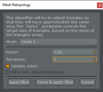
The first step of this is retopology. In the Project pane on the left, right click the mesh and select Filters > Retopology.
This is, as Blender’s documentation tells me, “the process of simplifying the topology of a mesh to make it cleaner and easier to work with”. The default for Iterations is 5, but I’ve found that leaving it at 5 winds up turning your circular base into a kind of wonky-shaped hexagon. So ratcheting it down to 2 seems to work a bit better. Like a good recipe in the kitchen, adjust this to taste.
Click Clone & apply filter. The reason you want to clone this now is that you really don’t want to hand-edit the mesh in Zephyr after you perform this step. So if you need to go back and fix something, you want an un-retopologied mesh to go back to.
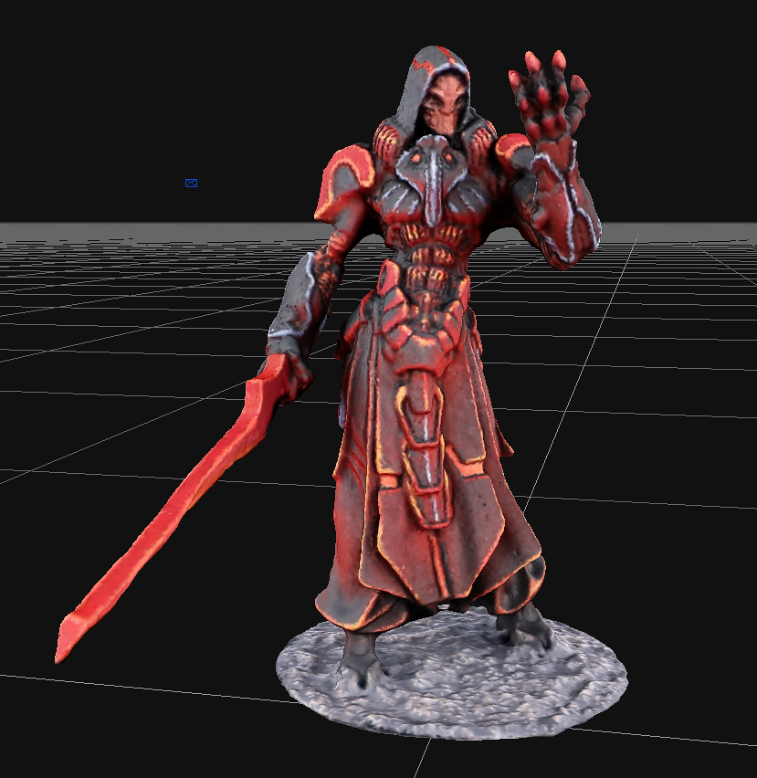
You’ll be left with a mesh that looks a Playstation 2 version of your model. That’s fine. Trust me, it’ll look better shortly.
Decimation
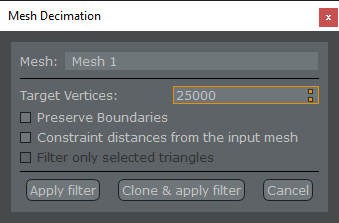
Tabletop Simulator limits the number of vertices per model, and any model exceeding that number will refuse to load. As a first step to reducing the number of vertices in our model, we need to decimate it. Decimation, as Blender’s documentation tells it, “allows you to reduce the vertex/face count of a mesh with minimal shape changes”. So again, in the Project pane on the left, right click the cloned mesh generated from your retopology, and select Filters > Decimation.
I don’t know the magic number of target vertices to type here, but I’ve not had any issues with 25000. Click Clone & apply filter.
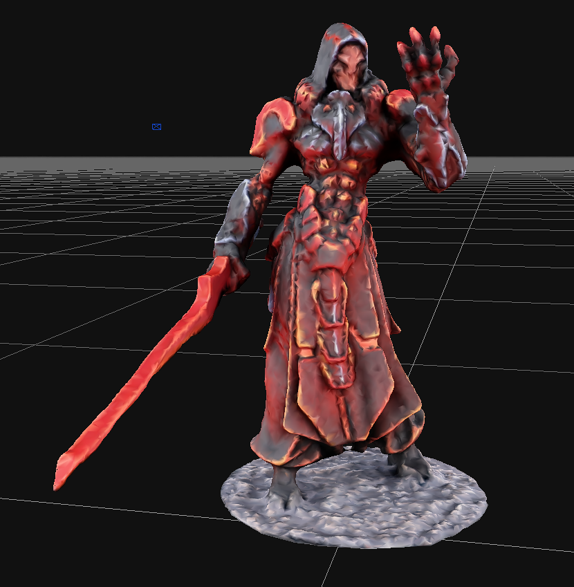
Okay, I know. I know. You now have something that looks like a Playstation 1 version of your model. It looks worse than before. Trust me, it’s fine. Just stick with it.
Textured Mesh Generation
We’re in Zephyr’s home stretch, just a couple more steps. We now need to generate the final mesh which will be exported. In the Workflow dropdown, select Textured Mesh Generation. Change the Settings in the top right to Advanced.
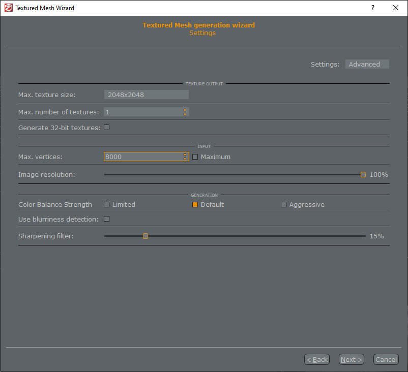
Here’s where the second (and real) line-in-the-sand gets drawn for Tabletop Simulator. Setting Max vertices too high here will prevent your model from loading in TTS. Setting it too low, however, and your model will look terrible. Through trial and error, I’ve found that 8000 is the highest I can go and have it always work in TTS. This is just my experience, so maybe adjust this down if TTS refuses to load your model. Click through the textured mesh wizard, let it run, and …
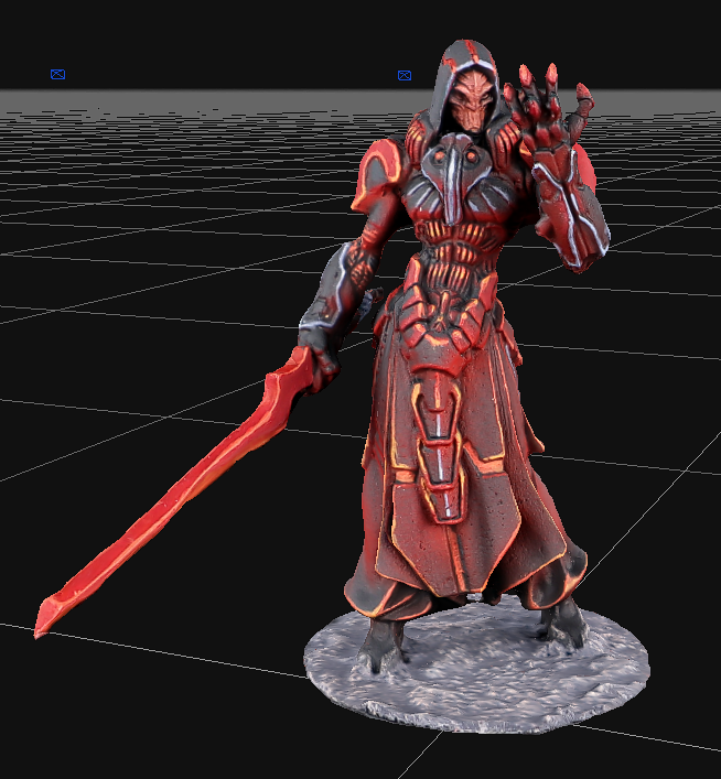
Voila! What you are looking at now is almost exactly how it will look in Tabletop Simulator. It should be a significant improvement over how it looked after retopology and decimation. Take a victory lap, as this is big hurdle. We’re not done yet, but the hard work for this leg of the race is over.
As you look around at your model, if you notice any errors, just go back in the Project pane to a previous step (preferably as early as possible), correct the errors by deleting points, and then go back through the steps until you get here again. While this does sound agonizing, as you finally made your way here, it’s much easier the second time through. And if you’re scanning a lot of models, you’ll be able to sprint through these steps in no time.
Export Textured Mesh
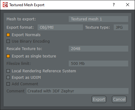
As a reminder, go to File > Save to make sure you don’t lose any of your progress. But now we need to generate a 3D object that Blender and Tabletop Simulator knows how to handle. In the toolbar, select Export > Export Textured Mesh.
There are a couple important settings here to call out. You need to change the Export Format to Obj/Mtl, Rescale Texture to 2048, and check Export as single texture. For a particularly large model like a vehicle, you can double the texture from 2048 to 4096 to try to squeeze just a bit more detail in there, but be careful. By doubling the size of the texture, you are almost quadrupling the memory footprint of the model. And like anyone who is trying to remember someone’s name at a party, Tabletop Simulator is pretty bad with memory.
Click Export and save it to your project directory, next to all your images and Zephyr’s zep file.
If you want to confirm that the export worked (and you’re on a PC), right click the obj file, and select Open With > 3D Viewer. You should see your model! If you don’t have 3D Viewer installed, or are on Mac, don’t worry. We’re about to do the real test in TTS.
Loading into Tabletop Simulator
We’re not quite done with the model, but before we go any further, we need to test it in Tabletop Simulator. Launch TTS, and select Create > Singleplayer > Classic > Sandbox. We don’t actually care about anything that loads in by default, so just delete whatever pieces are already there.
At the top of the screen, click Objects > Components > Custom. And then click and drag MODEL to the table. You’ll see a Custom Model popup.
We’ll become more familiar with this in the future, but for now, click the folder icon next to the Model/Mesh textbox, and select the obj file you exported from Zephyr. If you get asked whether you want to upload it to Steam Cloud, click Local (for the final product, you can upload it to Steam Cloud if you wish, but this is just a test to make sure it loads correctly).
For Diffuse/Image, select the jpg file that’s right next to the obj file. Even though this folder now has a lot of images in it, you won’t be able to miss this one. It’ll be a square picture, and kind of look like someone ran over your model with a steamroller. Again, click Local.
For Type, select Figurine. And then go to the Material tab and change it to Cardboard.
Click Import and …
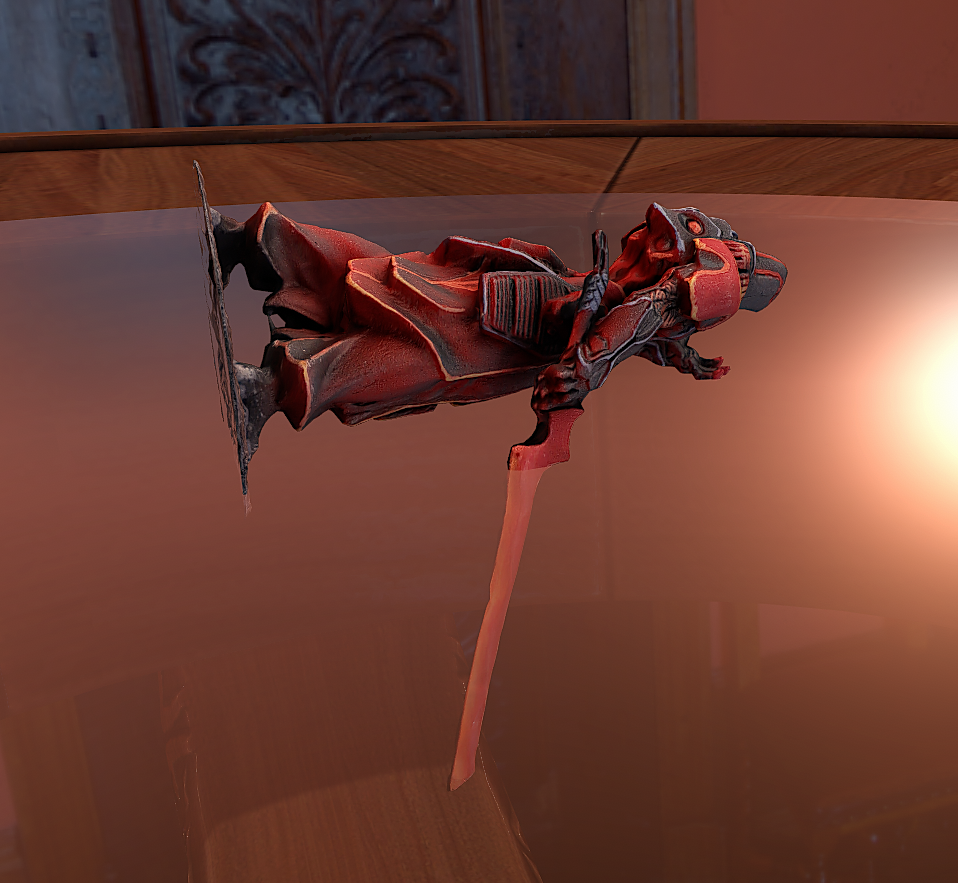
Success! I know the model is an odd size. I know it’s not facing the right direction and doesn’t have a base, but this right here is a success. We’ll be fixing all those issues in Blender soon.
If you get a Failed to load model error, then that means your model is hitting the vertex limit. Go back to the Textured Mesh Generation step above and try lowering Max Vertices setting a bit and try to import it again.
Next Time
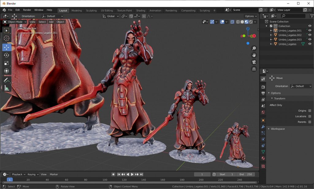
I know this article was a doozy, however I want to say that the hard part is behind us. That’s not true, but I do want to say it. Next time we’ll be dropping your 3D model in Blender, getting it oriented, shaving off some rough edges, and sizing it correctly. If you’re a Blender champ, then it’s smooth sailing from here on out. However if you’re like the rest of us, then don’t worry, I’ll walk you through it step by step.
Have any questions or feedback? Drop us a note in the comments below or email us at contact@goonhammer.com.
